The device
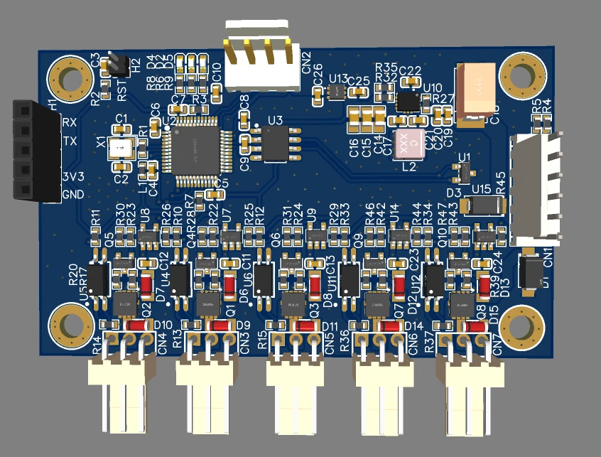
The controller drives five 24 V fans as independent channels. Each channel combines PWM speed control with tachometer monitoring, allowing the supervisory system to command airflow and detect missing or abnormal rotation.
Industrial control · Case study
A compact 24 V control board developed for independent speed control and operational supervision of five industrial fans.
Overview
The public description focuses on system-level design decisions and development work without exposing production files.
The controller drives five 24 V fans as independent channels. Each channel combines PWM speed control with tachometer monitoring, allowing the supervisory system to command airflow and detect missing or abnormal rotation.
Architecture
An STM32F103 coordinates five PWM outputs and five tachometer inputs. Dedicated MOSFET driver stages switch the fan channels, while the CAN transceiver connects the controller to the host system. A separate UART header supports commissioning and diagnostics.
The firmware handles channel commands, duty-cycle updates, tachometer pulse processing, fan-status evaluation and communication. A service mode makes it possible to command each channel independently and inspect measured status during bring-up.
Bench work included channel-by-channel functional tests, PWM and tachometer measurements, CAN/UART diagnostics and investigation of irregular fan behaviour. The analysis covered both firmware timing and hardware effects such as signal integrity, pull-up behaviour and unintended current paths through feedback lines.
Disclosure note: exact schematics, PCB source files, production firmware and protocol details are intentionally not published.
Gallery
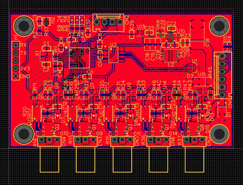
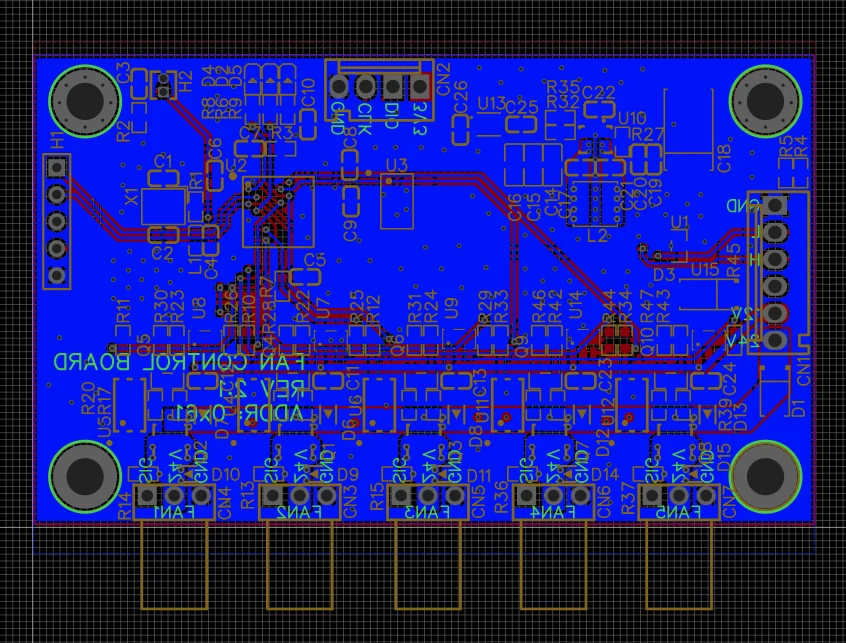
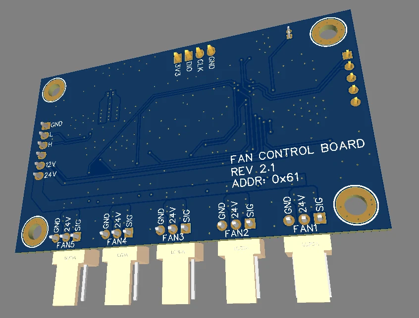
The gallery shows layout and 3D views of the prototype. Use the arrows, thumbnails or keyboard arrow keys to navigate.
Contact
Contact RK-PRO to discuss hardware architecture, PCB development, firmware, prototype bring-up or design review.